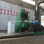
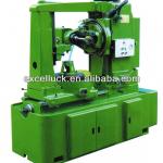
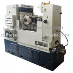
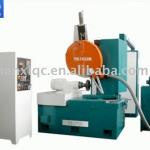
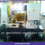
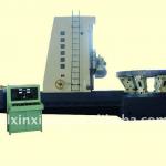
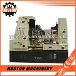
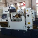
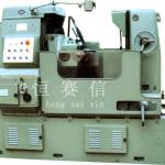
Y3180H trustworthy business partner low price gear cutting device/gear hobber
| Condition:New | Type:Gear Hobbing Machine | CNC or Not:Normal | Place of Origin:Hebei China (Mainland) |
| Brand Name:Judu | Model Number:Y3180H | Voltage:380v | Power(W):5.5kw |
| Dimension(L*W*H):2752mm*1490mm*1870mm | Weight:5500KG | Certification:CE | After-sales Service Provided:Engineers available to service machinery overseas |
| Max hobbing modulus:10MM | Min processing gear:12 | Max Processing Width:300mm | Max vertical travel of tool post:350mm |
| Spindle taper:Morse5 | Max axial movement of cutter:50mm | Worktable aperture:50mm | max swiver angel of tool post:±240deg |
| Rapid travel speed of tool post slide:not more than 540MM/Min | Worktable diameter:650mm |
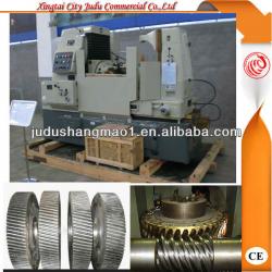
Y3180H trustworthy business partner low price gear cutting device/gear hobber
Introduction about the gear hobbing machine
A gear hobbing machine is a special form of milling machine that cuts gears. It is the major industrial process for cutting (as opposed to grinding) spur gears of involute form.
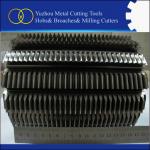
The machine forms the gear via a generating process by rotating the gear blank and the cutter (called ahob) at the same time with a fixed gearing ratio between hob and blank. The hob has a profile given in cross-section by the fundamental rack for the gear tooth profile and is in the form of a helix so that the sides of the teeth on thehobgenerate the curve on the gear. The helix has a number of cuts parallel to the axis to form the cutting teeth and the profile is suitably relieved to provide cutting clearance.
For a tooth profile which is a theoretical involute, the fundamental rack is straight-sided, with sides inclined at the pressure angle of the tooth form, with flat top and bottom. The necessary addendum correction to allow the use of small-numbered pinions can either be obtained by suitable modification of this rack to a cycloidal form at the tips, or by hobbing at other than the theoretical pitch circle diameter. Since the gear ratio between hob and blank is fixed, the resulting gear will have the correct pitch on the pitch circle, but the tooth thickness will not be equal to the space width.
Hobbing is invariably used to produce throated worm wheels, but it is not possible to cut all useful tooth profiles in this way; if any portion of thehobprofile is perpendicular to the axis then it will have no cutting clearance generated by the usual backing off process, and it will not cut well. The NHS Swiss tooth standards give rise to such problems. Such small gears normally must be milled instead.
Function about the gear hobbing machine
Gear-hobbing machines use a rotating, multiple-tooth cutting tool called a hob for generating teeth on spur gears, worm gears, helical gears, splines, and sprockets. More gears are cut by hobbing than by other methods because the hobbing cutter cuts continuously and produces accurate gears at high production rates.
Hobbing is a machining process for making gears, splines, and sprockets on ahobbing machine, which is a special type of milling machine. The teeth or splines are progressively cut into the workpiece by a series of cuts made by a cutting toolcalled ahob. Compared to other gear forming processes, it is relatively inexpensive but still quite accurate, thus it is used for a broad range of parts and quantities.
It is the most widely used gear cutting process for creating spur and helical gears and more gears are cut by hobbing than any other process since it is relatively quick and inexpensive.
Features about the gear hobbing machine
1.By continuous indexing, it is suitable to cutcylindrical spur, helical geras and sprocketsunder axis feeding.
2. It can also cutworm wheelsby a worm-wheel hub under radial feeding.
3. Machine feeding by manual.
4.It is suitable for mine, oil, ship, engineering mechanism industries for making large gears.
5.Tangential hob head is also available for special order to cut worm wheels under tangential feeding mode.
Technical parameters about the gear hobbing machine
| Model | Y31125ET | Y3180H |
Max workpiece diameter(with rear column/without rear column) | 1000MM | 550MM |
| 2200MM | 800MM | |
| Max hobbing modulus | 16MM | 10MM |
| Max Processing Width | 500MM | 300MM |
| Min processing gear | Z/K=12 | Z/K=8 |
| Max vertical travel of tool post | 800MM | 350MM |
| max swiver angel of tool post | ±60° | ±240° |
Distance between cutter axis and worktable | Max1000MM | Max585MM |
| Min200MM | Min235MM | |
| Spindle taper | Morse 6 | Morse 5 |
Hob diameter | Max Dia 245MM | Max Dia 180MM |
| Min length 220MM | Min length 180MM | |
| Max axial movement of cutter | 100MM | 50MM |
| Hob abor diameters | Φ27,Φ32,Φ40,Φ50MM | Φ22,Φ27,Φ32,Φ40MM |
Distance between hob axis center and worktable | Max 1250MM | Max 550MM |
| Min 100MM | Min 50MM | |
| Worktable aperture | 200MM | 80MM |
| Taper bore of workpiece mandrel | Morse 6 | Morse 5 |
| Worktable diameter | 950MM | 650MM |
| Spindle rotate speed and range | 7level 16-125R/Min | 8Level 40-200R/Min |
| Rapid travel speed of tool post slide | 520MM/Min | ≤540MM/Min |
| Worktable rapid moving speed | 470MM/Min | ≤540MM/Min |
Distance between worktable and outer support of axis face | Min700MM | Min400MM |
| Max1200MM | Max600MM | |
| Axial feed rate and degree | 8Level 0.39-4.39MM/R | 12Level 0.4-4MM/R |
| main motor power and synchro-speed | 11Kw 1500R/Min | N=5.5Kw 1500R/Min |
| Axial rapid motor power and synchro-speed | 3Kw 1500R/Min | N=1.1Kw 1500R/Min |
| Worktable rapid motor power and synchro-speed | 1.5Kw 1000R/Min | N=0.55Kw 1500R/Min |
| Hydraulic oil pump power and synchro-speed | 1.5Kw 1000R/Min | N=1.1Kw 910R/Min |
| Cooling pump power and synchro-speed | 1.5Kw 1500R/Min | |
| Machine weight | 15000Kg | 5500kg |
| Overall dimension | 3995*2040*2700MM | 2752*1490*1870MM |

| Packaging Detail:Wooden case suitable for long distances sea shipping or as customers' needs |
| Delivery Detail:within 3 days after receiving advance payment |


