
WINDOW CNC
| Condition:New | Type:Vertical | Place of Origin:Italy | Brand Name:FOM China |
| Model Number:FLEN |
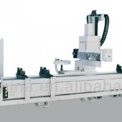

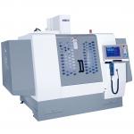
FLEN
BASIC SPECIFICATIONS
Structure
The structure is made of a machine bed with a sliding carriage in its rear section.
Both are in electrowelded steel duly stabilized after each work phase to ensure that there is
no interior tension; they are sized to guarantee stability and precision during machining
operations.
Axes sliding
The axes slide on high precision, robust, reliable linear guide-ways with recirculating
ball blocks equipped with oil scrapers and with medium/high preloading.
Axes movement
The independent axes are controlled by brushless Yaskawa servomotors by means of:
· Pinion, rack and mechanical system for backlash recovery for X axis (longitudinal)
· High precision ground recirculating ball screw and preloaded lead for Y (transversal) and
Z (vertical) axes. The Z axis drive is equipped with an electro-magnetic brake which is
enabled if mains power is cut-off.
The digital servomotors not only allow for short, optimal positioning and adjustment times,
but also high head positioning speed. The position of the axes is detected by means of a
rotating transducer.
The digital servormotors not only allow for short, optimal positioning and adjustment times, but also high head positioning speed. The position of the axes is detected by means of a rotating transducer.
Spindle Head
Constructed with a system of crossed tables in lightweight alloy to obtain a reduction in weight, high resistance to loads and accuracy in the mechanical work they perform, all at the same time. The solution used has considerable advantages in terms of machining precision and maintenance.
Electrospindle
Designed by Fom Industrie, this electrospindle ensures important performances, both at low number of revolutions as well as at high speed, to satisfy the increasing needs in terms of flexibility. The 4kW electrospindle is equipped with constant torque, rotation speed up to 12,000 rpm, adjustable, positioning 0°/ 90°/ 180° for machining the three profile sides, forced air cooling, ISO 30 DIN 69871 tool coupling and relative presence detecting micro-switch. The tools are locked into place mechanically, and released by means of a pneumatic system. Front and rear high speed precision bearings guarantee strict control of the electrospindle axial and radial stress during the work phases. The electrospindle rotation speed is managed by a static frequency changer (inverter), complete with:
• Display for visualisation of diagnostics in case of anomalies.
• Protection from voltage and current overloads.
• Automatically controlled tool rotation braking action.
• Resistor for braking power dissipation.
Tools Lubrication
One of two systems can be used: emulsified oil with liquid recovery by means of a
chips settling system, or pure oil by means of a sprayer with over-pressure device (minimal
lubrication).
Tools Magazine
Located in a gate-protected area in the carriage, it has 12 slots, can rotate in both
directions and is provided with an “absolut” encoder for detecting the position.
The rotation movement is managed by a static frequency changers (inverter) which guarantees more precision and positionig speed.
Working area
Situated on the machine bed and made up of:
· 4 pneumatic vices (expandable) for locking the profiles. They slide on ground roundsection
bars with ball couplings and pneumatic locking. Movement/positioning is
managed by the numeric control through a proper algorithm. Clamping jaws are
positioned using a patented pushbutton system. Patented pivoting clamping system
ensures optimum adhesion to the profile.
· 1 sliding pneumatic stop.
1.9 Electric cabinet
Equipped with filters for protection against emission and reception disturbances
(EMQ); it is separate from the command console and contains the machine drives, the static frequency changer (inverter), the Vision numeric control complete with the machine control devices; it has an IP 55 protection grade against dust and liquids.
1.10 Command console It incorporates the user interface made up of a PC, pendant push button strip,
Display and alphanumeric keyboard; it includes:
· Connection to laser bar code reader.
· Connection to remote control units (handhelds)
1.11 Protection and Safety Devices
In compliance with the requirements of EC directive 98/37 and successive modifications, the protection and safety devices are made up of:
• Acoustic insulation head cap.
• Mechanical cams and safety micro-switch for operator protection during alternating work phases.
• Photoelectric cell barrier.
• Rear and lateral barrier fences.
2.0 CONTROL EQUIPMENT
2.1 Omega 200
Made up of:
• Extractible shelves (right and left) for mouse support.
• Mobile control console
• Network to machine electrical cabinet with RJ 45 attachment for the network line
• Optical USB mouse
• Remote unit with display for axis movement (available on request)
• Pendant push button strip complete of potentiometer for the adjustment of the overfeed of the axes
It is possible to arrange a PC unsupplied with the follow characteristichs:
• Colour display with flat screen TFT 17’’
• USB English Keyboard
• Laser gun for bar code reading
PC PENTIUM 4 comprising:
• Front loading CD-ROM 24X
• Front loading 3,5’’ 1,44 MB disk drive
• 40 GB Hard disk (7.200 rpm) or higher
• 2 serial ports
• 8 USB ports (6 back, 2 front)
• 512 MB Ram memory
• Ehernet network card: 10/100 Mbps
• ATI Radeon X300 128MB graphic card
• Interior loudspeaker
• Follow programs :
• Windows XP Professional SP2.
• FomCam.
• Vision Interface 4 software for managing blocks of manual control and service on line - assistance interface
Note: The programs are to be installed on a P.C. which is not included and with the above characteristics.
2.2. FOM CAM
Graphic interface based on the Windows operating system for the design of the machining operation and the pieces which automatically generates the CNC program that can be executed by the machining centre. The system permits:
Program features:
· Easy to learn and easy to use, highly flexible
· 3D simulation of parts, tools and machinings
· Display the piece position on the machine
· Double cell machines management
· Vises and fixtures management
· Machining library for accessories
· DXF Profile Library
· Vise position optimization
· Automatic bar-code recognition
· Integration with ProF2 (window software)
· Cutting line and machining center management
· 5 axis machining
FomCam is the new easy-to-use CadCam solution for the 3D and 2D machining design
on profiles. FomCam supports all FOM machining centers, the FOM 3, 4 and 5 axis
machines and the cutting and machining lines. An intuitive software solution, FomCam
was developed in close collaboration with expert machine tool users and manufacturers
in the industrial and window manufacturing sectors. FomCam makes possible any kind
of machining and ensures the quality of the NC code.
Simplify the working process
It has never been that easy to use a machining center: FomCam's user interface is
extremely intuitive as it gives both 2D and 3D simulation options and offers a detailed
summary of the machinings added on the part.
Vise and part positioning in the machine
FomCam automatically generates the CNC codes to be executed on the machine,
considering single or double cell, left or right stop, or custom fixture setups for the
simultaneous machining of more than one part. FomCam finds automatically the best
strategies for vise positioning and simulates the toolpath before the machine starts the
job.
Parameterized machinings
The machinings are parameterized. They are easily modified, edited or repeated by
changing the numeric data in the model. FomCam applies the update to each
machining in real time.
Machining optimizations
To make the machining even faster, the software automatically minimizes the numbers
of tool changes and spindle movements saving considerable time.
Libraries
FomCam manages the Profile libraries with 3D and 2D views, the machine's Tool
Libraries and the Machining Libraries of the single profiles.
Add the machinings for memorized groups
FomCam lets you proceed rapidly with the machinings for an accessory: just select a
code from the accessories list and the X-position on the piece: all machinings referred
to the accessory, including the tool data, will be added automatically.
Maximum production control
FomCam directly controls the machining center as it transfers the CNC code and
controls its execution. It is not necessary to exit the program while the center is
working.
More productivity through automation
The machining cycle starts with the scan of the bar-code on the part. Based on the
bar-code data, the center starts the machinings that were defined for this part in the
Accessories Library. FomCam also allows to interrupt and re-start the machining list
and to view the status info of each part, i.e. the total of repetitions requested and the
number of repetitions executed so far.
High-efficiency double cell machinings
Save even more time and avoid production still-stands using the FomCam double cell
machining functions. These functions allow to position the vises in one cell while the
other cell is working without interruption.
FOMCAM - SIMULATION
Simulate every step of the NC code generation with the intuitive FomCam graphical
interface. The visualisations of the components, machinings and tools are 3
dimensional, and the view points can be changed with a simple mouse-click. The 3D
views also include different vise setups with multiple components.
Machining time calculation
Based on the simulation functions, FomCam calculates the exact cycle time of a
machining before starting it. FomCam also shows the time schedule within the various
machining stages. This calculation is also possible for a list of pieces, including the
repetitions, as an estimate of the production time of an entire order.
FOMCAM AND PROF2 INTEGRATION PACKAGE FOR WINDOW AND DOOR
MANUFACTURERS
A software solution that enables window and door manufacturers to take advantage of
FomCam, as it integrates with the window and door design program ProF2. This
integration package will design windows, doors and curtain walls, define the machining
strategies and generate the cutting and machining lists. Design the structure and
select the profiles with ProF2. Use FomCam to define the machinings for each selected
part and the program automatically calculates both the cutting and the machining lists.
The optimized cutting list is transmitted to the sawing machine. The sawing machine
bar codes and labels the part. The machining center reads the label and executes the
machinings as defined by FomCam
FOMCAM - OPTIONAL MODULES
FomCam also offers a series of optionals based on different needs.
Machinings from DXF
The Machinings from DXF module imports and reads any type of machinings starting
from a DXF. This tool allows to create any kind of form for a machining without
involving DXF.
Bar code reader
Reads the bar code and starts the machinings on the selected piece.
Wizards and guided compositions
This module offers some useful features:
In security shutters, it generates automatically the position of the blades.
It lets you insert pre-holes into steel machinings. It allows to design bands as a single
block and to perform the machinings dividing it into many pieces.
3.0 TURNKEY SYSTEM
FOM INDUSTRIE not only offers its Clients a machine tool, but also a "turnkey" productive system to solve all of the problems involved in production. The company's experience is at the client's disposition to optimize the relationship between machining centre performance and the technological machining requirements

| Packaging Detail:Plastic film. |
| Delivery Detail:30-60 days |
Related Product for WINDOW CNC
Rice Milling, Cold Store, Auto Bricks making & Milk Processing Plants & Industrial Machinery
Supplier of heavy industrial machinery in Bangladesh
Machining Center universal
Machining Center - Univ. WITZIG & FRANK Triflex U60NEW PRICE: > 2 Mio.
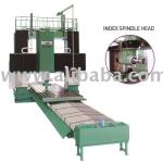
RAM SPINDLE TYPE DOUBLE MACHINING CENTER
HIGH PRODUCTIVITY, HIGH-ACCURACY MACHINING CENTER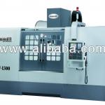
Vertical machining center
Wide column design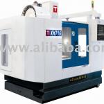
Vertical Machining Center (XH716, XHS716)
FANUC 0i mate-Mc system16tools armless type magazine
High rigidity and speed spindle unit
Oil spindle cooling equipment
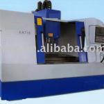
Vertical machine center/machine center/machining center/machine tool
Vertical machine center/machine center/machining center/machine toolstrong cutting,high torque at low speed...
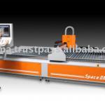
Portable CNC Plasma Cutting Machine
Portable CNC Plasma Cutting MachinePlasma cutter / CNC Cutting machin / Table type
VERTICAL MACHINING CENTER
We are professional manufacturer & exporter of PC-based controller,CNC Milling machine,Vertical Machining Center, EDM in Taiwan.
CNC vertical machining center
VMC-A850/D850/E850VMC-A1000/D1000/E1000/L1000
VMC- A1300/D1300/E1300.1301/L1300.1301
machining center cnc
machining center cnc / vertical machining center / cnc millingX/Y/Z travel: 500 / 400 / 450
Used CNC Machining Center YangCNC SMV-600
YangCNC SMV-600Year: 1998. 10
Controller: Mitsubishi
Rabbit widely used,CNC Router HX-6090 with CE, high speed,good quality,cnc router
1.Widely used in many fields2.Good quality,reasonable price
3.engrave/cut non-metal,engrave metal
4.3D available