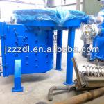
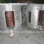
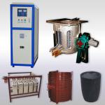
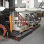
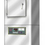
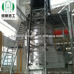
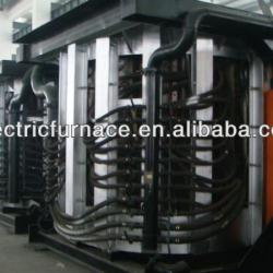
Medium frequnecy induction furnace
| Condition:New | Type:Induction Furnace | Usage:Melting Furnace | Place of Origin:Shanghai China (Mainland) |
| Brand Name:SEHM | Model Number:GW-0.5-250/1J | Voltage:380V | Power(W):250KW |
| Dimension(L*W*H):16cbms | Weight:38t | Certification:IEC, ISO900 | Shell material:steel |
5.4 The working principle of the start calculation.
After current overload protection signal are phase-inverted through IC13B, they are sent to the current overload cutting off trigger formed by IC5A to lock the trigger pulse and drive ‘current overload’ indicating lamp and alarming relay. After the current overload trigger acts, the circuit can put into operation only when the circuit is reset by the reset signal or is turned off and restarted. The potentiometer W2 is used to adjust current overload level.
When phase missing is found in the 3-phase AC input, the control board can do protection and indication for the power supply. Its principle is as follows:
The 3-phase voltage signals A,B and C are drawn from the cathodes of SCR4,6 and 2 separately, are isolated through the photoelectric coupler, and then was send to IC1 and IC16 for detection and identification. Once phase missing is found, trigger pulse will be locked and ‘phase-missing’ indicator and alarm relay will be drove.
In order to make the control circuit to run reliably and correctly, the control circuit is equipped with a start timer and an under-voltage detecting circuit. At the start, the control circuit is at unsteady condition. The circuit is equipped with a 3s timer. Trigger pulse will be applied after the timer stops. The part consists of C11,R20 and others. Too low DC voltage in the control board or the unusual operation of the voltage stabilizer cause because of some reason may make the control make mistake. The circuit is also equipped with an under-voltage detecting circuit and it consists of DW4, IC9B and others. When voltage Vcc is lower than 12.5V, trigger signal will be locked to avoid unusual trigger.
Auto repeatable start circuit consists of IC9A and can be turned off by DIP2 switch.
IC5B forms a voltage overload cutting trigger. It is used to lock the trigger pulse of the rectifying bridge and drive ‘voltage overload’ indicating lamp on and the alarm relay. It through Q9 makes the voltage overload protection oscillator IC18A start oscillation. Like the current overload trigger, after the voltage overload trigger acts, the circuit can put into operation only when the circuit is reset by the reset signal or is turned off and restarted. The trimming potentiometer W1 is used to adjust voltage overload level.
Q7 and its environmental circuits forms a low water pressure delay protection circuit. The delay time is about is about 8s. The reset signal is out of CON2-6 and CON 2-7. The reset will suspend when it is at closed state.

| Packaging Detail:Plywood package |
| Delivery Detail:45 days |


