
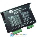
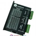
DM422C cnc stepper driver with good quality
| Place of Origin:Guangdong China (Mainland) | Brand Name:casun | Model Number:DM22C | Motor Type:Stepper Motor |
| color:black | certificate:CE,ROHS | Chopping frequency:15KHz | current:0.3A~2.2A |
| feature:low noise | key words:cnc stepper driver | sample:can be offered | specifications:can be customized |
| phase:2or 4 |
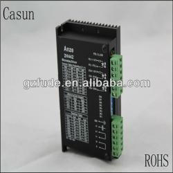

DM422C cnc stepper driver with good quality
1.ODM&OEM are welcome
2.Factory price
3.customized
Key Features:
Introduction of Digital Stepping Drives:
The DM422C is a versatility fully digital stepping driver based on a DSP with advanced control algorithm. The DM422C is the next generation of digital stepping motor controls. It brings a unique level of system smoothness, providing optimum torque and nulls mid-range instability. Motor self-test and parameter auto-setup technology offers optimum responses with different motors and easy-to-use. The driven motors can run with much smaller noise, lower heating, smoother movement than most of the drivers in the markets. Its unique features make the DM422C an ideal solution for applications that require low-speed smoothness. Compared to the DM432C, the DM422C has smaller size and lower cost.
Features of Digital Stepping Drives:
? Anti-Resonance, provides optimum torque and nulls mid-range instability.
? Motor self-test and parameter auto-setup technology, offers optimum responses with different motors.
? Multi-Stepping allows a low resolution step input to produce a higher microstep output for smooth system performance.
? Microstep resolutions programmable, from full-step to 102,400 steps/rev.
? Supply voltage up to +40 VDC.
? Output current programmable, from0.3A to 2.2A.
? Pulse input frequency up to 75 KHz.
? TTL compatible and optically isolated input.
? Automatic idle-current reduction.
? Suitable for 2-phase and 4-phase motors.
? Support PUL/DIR and CW/CCW modes.
? Over-voltage, over-current, phase-error protections.
Applications of Digital Stepping Drives:
Suitable for a wide range of stepping motors, from NEMA frame size 14 to 23. It can be used in various kinds of machines, such as laser cutters, laser markers, high precision X-Y tables, labeling machines, and so on. Its unique features make the DM422C an ideal solution for applications that require low-speed smoothness.
Electrical Specifications (Tj = 25oC/77oF)
Parameters | DM422C | ||||
| Min | Typical | Max | Unit | ||
| Output current | 0.3 | - | 2.2 (1.6 RMS) | A | |
| Supply voltage | +20 | - | +40 | VDC | |
| Logic signal current | 7 | 10 | 16 | mA | |
| Pulse input frequency | 0 | - | 75 | kHz | |
| Isolation resistance | 500 | Mohm | |||
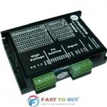
Pin Assignment and Description
Connector P1 Configurations:
| Pin Function | Details |
| PUL | Pulse signal:In single pulse (pulse/direction) mode, this input represents pulse signal, each rising or falling edge active (software configurable); 4-5V when PUL-HIGH, 0-0.5V when PUL-LOW. In double pulse mode (pulse/pulse) , this input represents clockwise (CW) pulse,active both at high level and low level (software configurable). For reliable response, pulse width should be longer than 7.5µs. Series connect resistors for current-limiting when +12V or +24V used. The same as DIR and ENA signals. |
| DIR | DIR signal:In single-pulse mode, this signal has low/high voltage levels, representing two directions of motor rotation; in double-pulse mode (software configurable), this signal is counter-clock (CCW) pulse,active both at high level and low level (software configurable). For reliable motion response, DIR signal should be ahead of PUL signal by 5µs at least. 4-5V when DIR-HIGH, 0-0.5V when DIR-LOW. Please note that rotation direction is also related to motor-driver wiring match. Exchanging the connection of two wires for a coil to the driver will reverse motion direction. |
| OPTO | Opto-coupler power supply, and the typical voltage is +5V. Series connect resistors (at the PUL, DIR, ENA terminals) for current-limiting when +12V or +24V used. |
| ENA | Enable signal:This signal is used for enabling/disabling driver. High level for enabling the driver and low level for disabling the driver. Usually leftUNCONNECTED (ENABLED). |
Connector P2 Configurations
| Pin Function | Details |
| +Vdc | Power supply, 20~40 VDC, Including voltage fluctuation and EMF voltage. |
| GND | Power Ground. |
| A+, A- | Motor Phase A |
| B+, B- | Motor Phase B |
Selecting Microstep Resolution and Drive Output Current
Microstep resolutions and output current are programmable, the former can be set from full-step to 102,400 steps/rev and the latter can be set from 0.3A to 2.2A.
However, when it?s not in software configured mode, this driver uses a 6-bit DIP switch to set microstep resolution, and motor operating current, as shown below:
Microstep Resolution Selection
When it?s not in software configured mode, microstep resolution is set by SW5, 6 of the DIP switch as shown in the following table:
Microstep | Steps/rev.(for 1.8omotor) | SW5 | SW6 |
| 1 to 512 | Default/Software configured | on | on |
| 8 | 1600 | OFF | ON |
| 16 | 3200 | ON | OFF |
| 32 | 6400 | OFF | OFF |
Current Settings
When it?s not in software configured mode, the first three bits (SW1, 2, 3) of the DIP switch are used to set the dynamic current. Select a setting closest to your motor?s required current.
Peak Current | RMS Current | SW1 | SW2 | SW3 |
Default/Software configured (0.3 to 2.2A) | ON | ON | ON | |
| 0.5A | 0.35 A | OFF | ON | ON |
| 0.7A | 0.50 A | ON | OFF | ON |
| 1.0A | 0.71 A | OFF | OFF | ON |
| 1.3A | 0.92 A | ON | ON | OFF |
| 1.6A | 1.13 A | OFF | ON | OFF |
| 1.9A | 1.34 A | ON | OFF | OFF |
| 2.2A | 1.56 A | OFF | OFF | OFF |
Notes:Due to motor inductance, the actual current in the coil may be smaller than the dynamic current setting, particularly under high speed condition.
| Packaging Detail:1.carton box with foam2.can be customized as you reuqire |
| Delivery Detail:7~15 days after receiving the payment |
Related Product for DM422C cnc stepper driver with good quality
Leadshine 2-phase DSP Based Digital Stepper Motor Drive DM Series DM856 DC18-80V 0.3-5.6A New
1. Leadshine Stepper Drive2. 2-phase DSP Based Digital Stepper Motor Drive
3. New in box
4. Fast shipping
Leadshine 2-phase DSP Based Digital Stepper Motor Drive DM Series DC18-30V 0.3-2.0A DM320C New
1. Leadshine Stepper Drive2. 2-phase DSP Based Digital Stepper Motor Drive
3. New in box
4. Fast shipping
Leadshine 3-phase Classic Analog Stepper Motor Drive 3ND883 DC18-80V 2.1-8.3A New
1. Leadshine Stepper Motor Drive2. 3-phase Classic Analog Stepper Motor Drive
3. New in box
4. Fast shipping
Leadshine 2-phase DSP Based Digital Stepper Motor Drive DM Series DC18-40V 0.3-2.2A DM422C New
1. Leadshine Stepper Drive2. 2-phase DSP Based Digital Stepper Motor Drive
3. New in box
4. Fast shipping
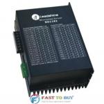
Leadshine 2-phase Classic Analog Stepper Motor Drive ND1182 AC70-150V 0.7-8.2A New
1. Leadshine Stepper Motor Drive2. 2-phase Classic Analog Stepper Motor Drive
3. New in box
4. Fast shipping
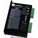
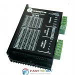
Leadshine 2-phase Classic Analog Stepper Motor Drive M542 DC20-50V 1.0-4.2A New
1. Leadshine Stepper Motor Drive2. 2-phase Classic Analog Stepper Motor Drive
3. New in box
4. Fast shipping
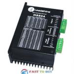
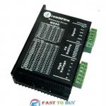
Leadshine 2-phase Classic Analog Stepper Motor Drive M880A DC24-80V 2.8-7.8A New
1. Leadshine Stepper Motor Drive2. 2-phase Classic Analog Stepper Motor Drive
3. New in box
4. Fast shipping
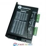
Leadshine 2-phase Classic Analog Stepper Motor Drive M860 DC24-80V 2.4-7.2A New
1. Leadshine Stepper Motor Drive2. 2-phase Classic Analog Stepper Motor Drive
3. New in box
4. Fast shipping
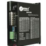
Leadshine 2-phase DSP Based Digital Stepper Motor Drive DM Series DM2282 AC80-220V 0.5-8.2A New
1. Leadshine Stepper Drive2. 2-phase DSP Based Digital Stepper Motor Drive
3. New in box
4. Fast shipping
Leadshine 2-phase Classic Analog Stepper Motor Drive M760 DC20-75V 1.45-6.0A New
1. Leadshine Stepper Motor Drive2. 2-phase Classic Analog Stepper Motor Drive
3. New in box
4. Fast shipping
Leadshine 2-phase Classic Analog Stepper Motor Drive M550 DC20-50V 1.2-5.0A New
1. Leadshine Stepper Motor Drive2. 2-phase Classic Analog Stepper Motor Drive
3. New in box
4. Fast shipping
Leadshine 2-phase Classic Analog Stepper Motor Drive M752 DC20-75V 1.8-5.2A New
1. Leadshine Stepper Motor Drive2. 2-phase Classic Analog Stepper Motor Drive
3. New in box
4. Fast shipping