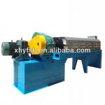
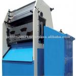
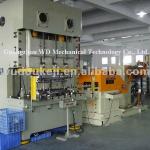
CNC angle punching marking and cutting machine for power transmission tower
| Condition:New | CNC or Not:CNC | Power Source:Hydraulic | Place of Origin:Shandong China (Mainland) |
| Brand Name:FINCM | Model Number:BL1412C | Voltage:380V | Power(W):33KW |
| Weight:14.5T | Dimension(L*W*H):25.4X7X2.2 | Certification:ISO90001 | Warranty:One year after installation |
| After-sales Service Provided:Overseas third-party support available | function:punching,marking and cutting | export experience:exported to 28 countries | Processing:Punching Machine |
| Usage:Special | Controlling Mode:CNC | Precision:Precision | Processing Types:Metal |
| Automatic Grade:Automatic | Workpiece and Weight:Large Machine Tool |
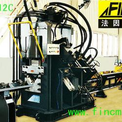
CNC angle machine for marking, punching and cutting has following specification:
1) Angle size: ∠40×4∠140×12 (Q345)
2) Max. punching diameter: φ25.5mm12mm thickness,Q345
Norminal punching force: 540KN
3) Norminal Punching force: 540
4) Nominal Cutting force: 750 kN
5) Max. length of the raw angle12m
6) No. of punching head per side2
7) The punching row per side: arbitrariness
8) No. of character group4
9) Dimension of characters14×10mm10 characters
10) Cutting modeDouble-blade cutting
11) No. of CNC axes3
12) Infeeding Speed: 40m/min
13) Overall size: 25.4X7X2.2m
Configuration for CNC angle line for punching marking and cutting model BL1412C
INFEED SYSTEM (for bars up to 12 mt)
Infeed transfer table for 12 m long bars
Rotating loading system for 12 m long bars
Automatic pincher clamping
Infeed conveyor with idle rolls
Carriage
Pincher
Device for bar length survey
WORKING UNITS
1. Working units base
· This base can hold the two punching units, the shear and the marking unit.
2. Marking unit with 4 marking groups
· Hydraulic marking unit having the following main technical features:
| Marking capacity | KN | 540kN |
| Type of standard character | 0-9 and A-Z | |
| Size of letter/number | mm | 14×10×19 |
| Characters per group "box" | No. | 10 |
| Selectable marking groups | No. | 4 |
3. Punching units
· Two hydraulic punching units: 1 unit to punch the angle bar right-hand flange, and 1 unit to punch the angle bar left-hand flange.
· Each punching unit is fitted with three (3) special removable punching tools and each of them is positioned thanks to ball screws and servomotor on an infinite number of gauge lines selected by the CNC.
· Each punching unit is fitted with a hydraulic multiple hold-downs system to clamp the angle bar thus ensuring the punch extraction.
· Main specifications of each tool:
| Capacity | KN | 540KN |
| Stroke | mm | 40 |
| Max. diameter with standard tool | mm | 25.5 |
| Max. thickness | mm | 20 |
| Gauge line stroke with respect to the anglebar edge | min. mm max. mm | 20 170 |
Each punching unit is fitted with nr. 3 punches and nr. 3 dies for the maximum round hole diameter.
4. Shearing unit
· The shearing unit is made of one hydraulic Double-CUT shear for angles complete with hold-down.
· Shearing capacity Max. available shearing Force 750KN
OUTFEED CONVEYOR
Idle rolls outfeed table for 6 mt long bars (one-side tiltable)
HYDRAULIC AND PNEUMATIC SYSTEM
1. Hydraulic power pack
a. Hydraulic power pack, to generate the high working pressure as well as the low pressure for the punching cylinder and for the auxiliary circuitries.
b. Hoses and connections.
c. Cooling system with air-cooling heat exchanger.
d. On board hydraulic system complete with solenoid-valves and wholly connected hoses.
e. Working Pressure (high) 21Mpa
f. Working Pressure (low) 5.5Mpa
2. Pneumatic system
· The system consists of:
a. Solenoid valves and machine system wholly connected.
b. Required Working Pressure ≥0.7Mpa
ELECTRIC SYSTEM
1. On board distribution system
2. Electric cabinet
· Cabinet containing power and control equipments for the units positioning axes and for the auxiliary services.
· The standard equipment is manufactured according to ISO9001-2000 standards. Special requests concerning both special rules and special protections will be considered upon Customers request.
· The power supply is 380 V - 50 HZ - 3 Phases.
· The Total Power Consumption 33 KW.
3. Control Unit
· The control unit with the control program supply the following characteristics:
Programming
Simplified data input (with tables and workpiece on-screen graphics)
Incremental values
Diameters programming
Linear, matrix and flange patterns
Nesting of equal or different workpieces into the same bar, with onscreen graphics
Automatic nesting
Processing
Automatic tool assignment
Unit offset sum
Values ordering
Execution
Automatic survey of the bar length, and re-calculation of the optimized accumulation
Automatic cycle stop for setup modification
Current program indication, with clear description of the program running at the moment
PLC inside and outside alarms and Diagnostic messages to the operator
TECHNICAL DOCUMENTATION
· The system is supplied with the following technical documentation:
Programming, maintenance, use and instruction manual
Electric diagrams
Hydraulic & Pneumatic diagrams
Engineered Drawing with complete details for the wearing parts and production tools.
MAIN OUTSOURCING COMPONENTS
1. AC Servo Motor Panasonic Japan
2. PLC Yokogawa Japan
3. Photoswitch SICK Germany
4. Contactor TE Company France
5. Solenoid Valve ATOS Italy
6. Towline Kabelschlepp Germany
7. Air cylinder and valves SMC Japan

| Packaging Detail:container |
| Delivery Detail:60 days |


