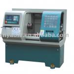
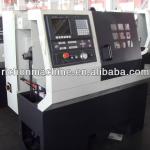
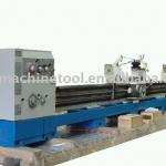
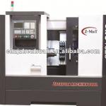
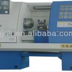
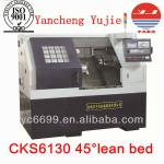
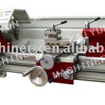
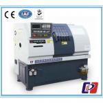
C5116B vertical lathe
| Condition:New | Type:Vertical | CNC or Not:Normal | Automatic Grade:Manual |
| Max. Swing Diameter:1600mm | Place of Origin:Liaoning China (Mainland) | Brand Name:Wa | Model Number:C5116B |
| Voltage:380V,440V,etc. | Power(W):main power30kw | Dimension(L*W*H):2660x2740x3528 | Weight:13t |
| Certification:ISO9001,CE | After-sales Service Provided:Engineers available to service machinery overseas |
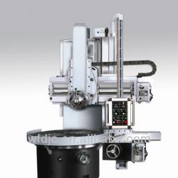
C5116B vertical lathe Technical specification
This specification is forφ1600×1000mm Single column vertical lathe, the supplier will produce this machine following the national relevant manufacturing norm.
1. Brief introduction
This machine is single column vertical lathe, the cutting diameter max. is 1600mm, the height of workpiece max. is 1000mm, this machine is suitable to machine ferrus and non-ferrus material with high speed tool and carbide tool.
Cylindrical surface and conical surface can be done in this machine, other operations like surface cutting, cutting-off also can be performed on this machine
2. Machine parameter
| No. | Item | Parameter |
| 1 | cutting diameter of vertical tool head | 1600mm |
| 2 | cutting diameter of side tool head | 1400mm |
| 3 | working height | 1000mm |
| 4 | working table diameter | 1400mm |
| 5 | max. weight of work piece | 5000kg |
| 6 | table speed | 5-160r/min |
| 7 | table speed steps | 16 steps |
| 8 | feed rate of both tool heads | 0.8-86mm/min |
| 9 | cutting force of tool head | 25000N |
| 10 | cutting force of side tool head | 20000N |
| 11 | torque of table | 25000N.M |
| 12 | tool head stroke vertical direction | 800mm |
| 13 | tool head stroke horizontal direction | 915mm |
| 14 | side tool head stroke vertical direction | 630mm |
| 15 | side tool head storke horizontal direction | 900mm |
| 16 | elevation stroke of cross beam | 900mm |
| 17 | swivelling angel of tool head | ±30° |
| 18 | rapid traverse of tool head | 1800mm/min |
| 19 | tool arbor dimension | 30x40mm |
| 20 | main power | 30kw |
| 21 | machine dimension | 2660x2740x3528 |
| 22 | machine weight | 13t |
3. main structure and performance
3.1 layout of machine
This machine is mainly composed of following parts: Column, Main drive gear box, elevation mechanism of cross rail, tool heade, electric system, Hydraulic system and etc. The main drive gear box is fastened through the bolts on the end of the column,working table is set on the front of column, the cross rail can move along the vertical slideway of column,the tool head is set on the cross rail which can feed to cut the work piece or fast traverse along the cross slideway of cross rail. The table is driven by 16 steps main gear box through 30KW AC motor, one suspending operation pendant is set in the front of the machine, which is used to control the machine.
3.2 main structure performance
3.2.1 main drive gear box
The main drive gear box is driven by 30KW AC motor,in the gear box, the engagement of different gears are realized through the hydraulic clylinder by operating the rotary switch on the pendant,to enlarge the working table speed range and working torque, there are altogether 16 steps of differnt gear engagement available.
3.2.2 feed mechanism
The two directions of movement of vertical tool head are driven by AC motor on the feed gear box which is connected with the right end of cross rail, the rapid traverse and feed motion of tool head are seperately controlled by two different motors on the feed gear box.
3.3 main character of machine
3.3.1 working table
Dynamic pressure guideway is used in the table base to ensure the least 5 ton loading capacity of machine, two pieces of Model of 3182100 short cylindrical radial roller bearings are used to ensue the rotation precision of working table, For there is inner conical surface in the two bearings who can be used to adjust the radial clearance of spindle,ample oil lubrication in the table base can ensure the good lubrication of table bearing when the table rotate, four seperate manual chuck jaws are used on the table.
3.3.2 Column
The column is connected with the table base, which is together with the table base form the strong and static structure of machine, the material of the column is high density and low stress casting iron, the vertical slideway on the column is made by hand scrape to ensure the perpendicular precison of cross rail goes up or down which is driven by AC motor on the top of the column through the elevation worm gear box.
3.3.3 cross rail
Cross rail can move up or down along the vertical slideway of the colum and is directly driven by the lead screw, to ensure of not falling down of the cross rail when elevatin the cross rail,safety floating nut is mounted on the cross rail to prevent falling down of the cross rail,when in working conditions, the cross rail will be clamped on the column through the belleville spring, when needing elevating the cross , there will be one cylinder piston push the belleville spring release from the column.
3.3.4 tool head
There are two tool heads equipped on this machine, one is vertical tool head another is side tool head. Both of the tool heads are three layer structures,they are mainly composed of cross saddle, swiveling saddle and ram. The swivelling saddle and cross saddle are both made of high density and low stress casting iron and the ram is made of nodular cast iron.
3.3.5 hydraulic system
The hydraulic system is mainly composed of table dynamic pressure system, main drive gear changing system, the cross rail releasingsystem, tool head counter balance system and so on,.
3.3.6 ways of lubrication: Main drive automatic lubrication system and tool head hand oil pump.
4. accuracy
Run-out of table in the diameter of 1000mm, the allowable deviation is 0.02mm, every increment of 1000mm, the allowable deviation is 0.01mm
Run-out of table side surface, the allowable deviation is 0.02mm, every increment of 1000mm, the allowable deviation is 0.01mm
The vertical movement of cross rail to the table surface
0.06mm/1000mm in the plane perpendicular to the cross rail
0.04mm/1000mm In the plane parallel to the cross rail
The parallelism of the rame head moving to the table surface, in any measurement of 1000mm is 0.03mm
perpendicularity of the movement of ram to the table surface
In the plane parallel to the surface 0.01/1000mm
In the plane perpendicular to the cross rail 0.05/1000mm
Perpendicularity of side head movement to the table surface 0.01/300mm
5.Packing for delivery(photo)

| Packaging Detail:wooden packing or container directly, the detailed ways can be discussed. |
| Delivery Detail:best sale product, if there is no storck, delivey 3 months |


