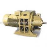
VHS 280 vertical hollow shaft motors
| Place of Origin:Tianjin China (Mainland) | Brand Name:QN | Model Number:VHS280 | Type:VHS motor |
| motor:IP23 | verital hollow shaft motor:VHS |

General Description
VHS serial vertical hollow-shaft motors are three phase squirrel cage induction motors specially designed for driving deep-well waterpump.The protection degree is IP23 and IP54.
These motors are of high efficiency, high starting torque, quiet-running, low vibration and low temperature rise, and can sustain heavy axial thrust load etc.
Specifications, Designations and Operation Conditions
Operation Conditions
Duty Cycle: Continuous (S1)
Ambient temperature: Not over 40°C
Altitude: Not over 1000meters above sea level
Field Condition: This type of motor is suitable for outdoor use in relatively dry climates without addition protection.
Cautions for mounting
The following preparation should be made before mounting:
1. Check carefully all data on the nameplate of the motor; make sure they are strictly in agreement with the requirements.
2. Inspect carefully that all the motor parts are assemble in good condition and make sure that no fastenings, such as bolts and nuts, become loosed or detached during transportation. Try to turn the motor in the direction by hand so as to determine whether the rotor rotates freely or not.
3. Measure the phase –to –phase and phase –to –ground insulation resistance by using a 500V megger. The readings should not be dried out. The commonly used drying method is to disassemble the motor and to try out it in an oven, maintaining the temperature at about 100°C. In general, the heating process lasts 12 to 24 hours.
If there is no drying oven, incandescent lamps may be placed inside and around 10% of the rated value to stator windings with the rotor locked. Drying will be accomplished by the current generated heat.
In either of the later two cases, precautions must be taken not to overheat the winding.
4. Before mounting, it is necessary to turn the motor at no load.
a) First unscrew the screw for exhaust hole, then unscrew the plug of grease nipple, fill with N15 lubricating oil to a middle scale mark of the oil gauge. Screw firmly the screw after oiling .Don’t under no oil conditions or with too much.
b) The correct connections are shown in “operation and instruction’’.
c) After inspection of the connection of terminals, the motor may be run at no load. If the motor does not start, turn off the power immediately and interchange any two of line connections, if the motor still remains at a standstill state, check carefully the power supply circuit.
d) When the motor is started for the first time, and has reached to the rated speed, cut off the power and reinspect. Note that no connections loosed, and there is no scraping between the parts, make adjustments necessary.
e) Running at no load should continue for 2 to 3 hours. During this period, check for any irregularities or unusual noise. After completion of this trial, inspect the bearing carefully to ensure have not been over-heated.
f) Let the lubricating oil fill into a clean container through the oil draining for reserve.
Motor Mounting
1. Make sure that the specifications and the capacity of the starting equipment meet the requirements on the nameplate.
2. Drain off the oil in the motor’s oil chamber before lifting, in lifting a motor be sure to attach the books of the crane to lifting lugs of the motor.
3. In the course of installation, the motor should be handled gently and placed vertically. Never let it rest upside down or lopsided.
4. When lifting the motor to the pump, the relative requirements of deep-well pumps should be obeyed.
5. Reoil just as above.
Operation and instruction
1. The motor should be grounded properly, an earth connecting terminal is located at the right lower portion in the terminal box. It can also be grounded to screws. Connection the motor base and pump if necessary.
2. The terminal board is equipped with six terminals which are marked respectively as following:
| Winding Phase Sequence | A | B | C |
| Beginning | U1 | V1 | W1 |
| End | U2 | V2 | W2 |
3. The motor’s correct rotating direction should be as follows.
When the power phase sequence A, B, C is opposite to the motor windings sequence, it should rotate counter clockwise facing from the top of the motor.
4. Starting is carried out at the full voltage. As the motor is started at full voltage, the starting current will be 5 to 7 times of the rated current. If the power supply is insufficient, the motor is permitted to start at reduced voltage. And the locked-rotor torque is directly proportional to the square of the voltage.
5. In general the power supply control unit should be provided with over current or short circuit protection devices, which should be regulated in correspondence with the rated current on the motor’s nameplate.
6. The motor can’t provide the rated output continuously if the deviation of the frequency between the power supply and the nameplate value exceeds 1% or the difference between the voltage of the power supply and the nameplate value is over 5%.
7. when the motor operates with load, an intermittent abnormal noise and vibration should not exist.
8. The motor are designed of class B or F insulation. The winding max. Allowable temperature rise is shown as in the following table.
| Test Methods | Stator winding Max. Allowable Temperature Rise | |
| Resistance | 80K(B Class) | 105K(F Class) |
Trouble shouting chart
CAUSES REMEDY
Motor fails to start
*the wiring is anti-phase connections Interchange any two of the line
*One-phase cut off Check the switch, fuse and wiring etc.
*Overload reduced the load or selects a large capacity motor.
*Supply voltage too low Adjust up to rated voltage±10%
*pump trouble Check the pump
The operation aped with load is lower than the rated speed
*supply voltage too low adjust up to rated voltage±10%
*Broken bar of the cage Replace the rotor
*Overload reduced the load or selects a larger capacity motor.
*Pump trouble Check the pump.
The sound is unusual during operation
*One-phase cut off Check the switch, fuse and wiring etc.
*Bearings are short of oil Fill fresh oil.
*Bearings worn out Replace bearings.
*Pump trouble Check the pump.
The temperature rise is too high or motor smoking
*Overload reduced the load or selects a larger capacity motor.
*One-phase cut off Check the switch, fuse and wiring etc.
*Air passages are blocked Remove the greasy dirt and dust in air passages.
*High ambient temperature Reduce the temperature
*Short circuit between turns or phases of windings Repair the windings
*Supply voltage too low or high Adjust up to rated voltage±10%
Bearings are overheated
*Worn bearings replace the bearings
*Lubricant oil deteriorated or bearings are short of oil Reoil
Non-reverse backstop is out of order
*there is dirt on the cylin drical pin Remove the dirt.
*The groove hole of an ant reverse ratchet plate id worn Replace the anti-reverse ratchet plate
There is leakage of oil in the bearing house of the end bracket
*The motor is inclined during transport Put out the oil in the oil chamber before transport
Over oil reduce the oil
The oil conduit is leakage Check the static seal and oil conduit
The woolen felt seal is worn Replace the woolen felt.

| Packaging Detail:Packing:for the seaworthy wooden cases20GP & 40GP container |
| Delivery Detail:30 days |


