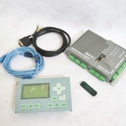
Leetro Laser Controller MPC6525
| Place of Origin:Guangdong, China | Brand Name:Leetro | Model Number:MPC6525 |

Leetro Laser Controller MPC6525:Laser controller mainboard+laser controller panel+laser power cable+usb cable+dongle
Leetro Laser Controller MPC6525, advanced stand-alone 3-axis motion controller designed for Laser Engraving and Cutting applications. Incorporating the advanced Field Programmable Gate Array (FPGA) and a 32-bit DSP, MPC6525 provides dedicated motion control features. Motion Controller MPC6525 is famous as high performance, high stability, longer lifetime, high cost performance; it is the bestLaser Control SystemforLaser Engraving and Cutting Machine.
1. Features:
A)Stand-Alone Motion Controller
B)Apply DSP and FPGA technologies
C)3-axis card for stepper motors or digital servo motors
D)Trapezoidal or S-curve drive of slow-up/slow down control
E)Switch interfaces such as origin and limit
F)1-CH laser power on/off control output
G)1-CH laser PWM control output
H)Support 1or 2-CH independent power analog output
I)PWM preheat control
J)Uncapping protection
K)Mono 24V DC power
L)RS232 applicable for mainstream industrial touch-screen supporting Modbus communication protocol
128M memory
M)Flying-optics compensation
N)Download data with USB flash disk or USB data cable
O)USB transfer speed up to 500Kb/s
P)Position compare output
Q)Look-ahead algorithm and trajectory fitting algorithm
R)Synchronization tracking
S)Look-ahead capability
2. Hardware Interface:
Pluggable terminal blocks of MPC6525 Laser Controllers make the connection easier for users. All I/Os are optically isolated signals.
Pin Array
Pin No./Pin Description | ||||||
| 1 | 2 | 3 | 4 | 5 | 6 | |
| +24V | 24V GND | |||||
| X1 | Foot-pedal switch | Uncapping protection | Reverse | 5V/24V GND | +5V/24V | |
| X2 | Z-axis forward limit | Z-axis reverse limit | Z-axis origin | 5V/24V GND | +5V/24V | |
| X3 | Y-axis forward limit | Y-axis reverse limit | Y-axis origin | 5V/24V GND | +5V/24V | |
| X4 | X-axis forward limit | X-axis reverse limit | X-axis origin | 5V/24V GND | +5V/24V | |
| X5 | Blow-off | END | USB flash disk instruction light | Reverse | 5V/24V GND | +5V/24V |
| Y1 | Laser power GND | Analog output | Laser power | Laser power on/off | ||
| Y2 | Z-axis pulse | Z-axis direction | 5V GND | +5V | ||
| Y3 | Y-axis pulse | Y-axis direction | 5V GND | +5V | ||
| Y4 | X-axis pulse | X-axis direction | 5V GND | +5V | ||
X1: Input power interface (24VDC)
Note:MPC6525 Motion Controlleradopts mono 24VDC power supply. The other power pins are output
JP1:
Note: JP1 is related with X3, X4 and X5. If 24V voltage is required for input signal ports X3, X4 and X5, the jumper should be connected to Pin1 and Pin2. If 5V voltage is required, the jumper should be connected to Pin2 and Pin3. If the jumper is removed, disconnect Pin5 of X3, X4 and X5.
JP2:
Note: JP2 is related with Y2. For analog-control laser power, remove the jumper,connect laser power to Pin2. For PWM-control laser power, connect the power to Pin3.
JP3:
Note: JP3 is related with Y1. If output Y1 to drive a 24V relay, the jumper should be connected to Pin1 and Pin2. To drive a 5V relay, the jumper should be connected to Pin2 and Pin3. If the jumper is removed, disconnect Pin6 of Y1.
JP4:
Note: JP4 is related with X2. If 24V is required for the general input X2, the jumper should be connected to Pin1 and Pin2. If 5V voltage is required, the jumper should be connected to Pin2 and Pin3. If the jumper is removed, disconnect Pin5 of X2.
3. Wiring:
Limit and Origin switches applied with MPC6525Laser Control Systemcan be contact switch or NPN proximity sensor.
Digital outputs of MPC6515 can drive intermediate relay or photo coupler. Refer to the following wiring diagram.
Stepper motor drives or digital servo motor drives receive Pulse/Direction outputs generated from MPC6525 Laser Controller. Refer to following wiring diagram of Pulse/Direction signals.

| Packaging Detail:standard export case |
| Delivery Detail:5 days |


