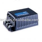
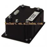
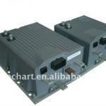
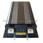
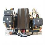
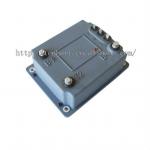
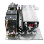
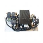
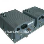
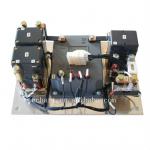
electric car motor controller
| Place of Origin:Shandong China (Mainland) | Brand Name:keya | Model Number:DC48DP360BL-R01ZC | Motor Type:DC Motor |
| Type:Motor Controller | VOLT:48V | current:300A |
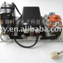
Electric car motor controller
Please Carefully read this manual before using this product.
The controller assembly is composed of chopper, main contactor, reversing contactor, main circuit fuse, pilot circuit fuse and aluminum heating sink.
1.1 The controller assembly shall be installed in ventilated and dry place, near storage battery and motor, and away from rainwater.
1.2 The wires of pilot circuit and main circuit shall be properly connected according to the wiring diagram. First connect pilot circuit,
and then connect main circuit with controller after inspecting the wiring to ensure its correctness.
The sectional area of main circuit wire depends on the motor power and it is usually not less than 25mm2.
The sectional area of control circuit wire is not less than 1 mm2.
1.3 Use multimeter to measure the direct current voltage on the either end of the storage battery to ensure
its conformity with the required operating voltage for controller assembly.
1.4 Close key switch, and contactor pull-in sound shall be heard.
1.5 If the indicator light (green light) in the front of chopper is ON, it indicates normal conditions for the next step of debugging.
1.6 Lift up the vehicle to let the driving wheels off the ground.
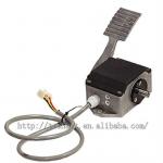
1.7 Use remote control panel to individually control the forward or backward speed of the controller assembly.
2. Usage
2.1 Put down the lifted vehicle and let the driving wheels on the ground. Drive the vehicle according to the methods described in 1.7 and 1.8.
2.2 With the function of under-voltage protection, the controller assembly will
stop working when its input voltage is lower than the 80% of its operating voltage.
2.3 With the function of over-voltage protection, the controller assembly will
stop working when its input voltage is higher than the 120% of its operating voltage.
2.4 With the function of over-temperature protection, the controller assembly will
stop outputting when the chopper temperature is higher than 75 and
the controller assembly will automatically restore its current output
after the chopper temperature declines.
2.6 If the vehicle needs reversing during the running process, it shall be stopped before reversing.
4. Main Technical Parameters for Controller Assembly
| Applicable voltage range Chopper operating frequency Electric lock input voltage Electric lock input current Over-voltage protection Contactor driver operating voltage Contactor driver current Applicable ambient temperature for controller assembly Maximum allowable temperature for chopper Voltage range for acceleration signal input Voltage range for potentiometer signal input | ±20% of operating voltage 15KHZ same as system voltage 60mA (typical value), pre-charge about 350mA in 3 seconds after starting 120% of operating voltage same as controller operating voltage 2A(over-current protection 3A) -25~50 75 1~5V 0~5V |

| Packaging Detail:CARTON |
| Delivery Detail:3 DAYS |


